Ethernet LAN switching covers layers 1 and 2 of the OSI model. A LAN is a network contained in a relatively small area like your home or office. This section will show you how end hosts communicate with each other in a LAN. Note that switches are used to forward traffic within a LAN.
Example of a simple LAN
Here we have a single switch that has three computers connected to it. Each computer has a MAC address associated with it that uniquely identifies the PC.

The MAC address (media access control address) is the worldwide unique hardware address of a single network adapter. The physical address is used to identify a device in computer networks.
- The first 6 numbers represent the manufacturer
- The last 6 numbers are unique to the device and identify the device itself
If PC1 wanted to communicate with PC2, below is the process to make that happen:
- PC1 sends a unicast frame to Switch 1
- The frame includes the destination and source MAC addresses
- Dest: 00:50:79:66:68:01
- Src: 00:50:79:66:68:00
- The frame includes the destination and source MAC addresses
- Switch 1 adds the MAC address of PC1 to the MAC address table
- This is known as a dynamically learned MAC address
- Switches learn where devices reside in the network by looking at the source MAC address
| MAC | Interface |
|---|---|
| 00:50:79:66:68:00 | e0 |
- Since the switch does not know where the destination MAC address lives, it will flood the frame. This means it will send the frame to all network devices it is connected to except the one that sent the frame.
- In this example, it sends the frame out of the e1 and e2 network interfaces
- PC3 ignores the packet because the MAC address of PC3 does not match the destination MAC address
- PC2 receives the packet and processes it through the OSI stack
- If PC2 does not respond back to PC1, the process stops here. This also means Switch 1 does not add the MAC address of PC2 to the MAC address table. Remember switches only add source MAC addresses to the table.
If we repeat the process and PC1 tries to communicate with PC2, what happens?
- PC1 sends a unicast frame to Switch 1
- The frame includes the destination and source MAC addresses
- Dest: 00:50:79:66:68:01
- Src: 00:50:79:66:68:00
- The frame includes the destination and source MAC addresses
- Switch 1 does not need to add the source MAC address to the table since it is already there
- Switch 1 sends a broadcast frame since it still does not know where the destination MAC address lives
- PC3 ignores the frame and PC2 accepts the frame and processes it through the OSI stack
What if PC2 then tries to communicate with PC1?
- PC2 sends a unicast frame to Switch 1
- The frame includes the destination and source MAC addresses
- Dest: 00:50:79:66:68:00
- Src: 00:50:79:66:68:01
- The frame includes the destination and source MAC addresses
- Switch 1 adds the MAC address of PC2 to the MAC address table
- Switches learn where devices reside in the network by looking at the source MAC address
- The Interface column means this is the interface the switch can reach the device but it does not necessarily mean this is exactly where the switch is located. This will make more sense in the next example.
| MAC | Interface |
|---|---|
| 00:50:79:66:68:00 | e0 |
| 00:50:79:66:68:01 | e1 |
- Since the switch knows where PC1 lives (by the MAC address table) it simply forwards the frame to PC1.
- This is an example of a known unicast frame and there is no need to flood the frame
- Note the rows in the MAC address table are removed from the table after a certain amount of inactivity
- The exact time, let’s say 5 minutes, will vary depending on the switch
Unicast frame - a frame destined for a single target Unknown unicast frame - an frame which the switch does not have an entry for Known unicast frame - a frame which the switch knows the location of a network device Broadcast frame - a frame that is sent out to all connected devices except the one that sent the frame
Switches do not separate LANs but they can be used to make the LAN larger. Let’s look at another example.
ARP (Address Resolution Protocol) - Is used to discover the layer 2 address (MAC address) of a known layer 3 address (IP address)
ARP Process consist of two messages:
- ARP Request - Sent by the device that wants to know a MAC address
- Is sent as a broadcast, sent to all hosts on the network
- ARP Reply - Sent to inform the requestor what the MAC address is
- Is send as a unicast, sent to only one host (the host that sent the request)
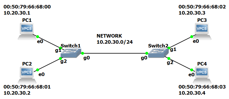
If PC1 wanted to send data to PC3, below is the process to make that happen
- PC1 sends an ARP request to Switch1
- The request includes the destination and source IP addresses
- Dest: 10.20.30.3
- Src: 10.20.30.1
- The request includes the destination and source MAC addresses
- Dest: FF:FF:FF:FF:FF:FF
- Src: 00:50:79:66:68:00
- At this point PC1 does not know the MAC address of PC3. It only knows the IP address of PC3.
- MAC FF:FF:FF:FF:FF:FF = the broadcast MAC address
- Since we are operating in layer 2 of the OSI model, we need to know the source and destination MAC addresses because switches communicate using MAC addresses and not IP addresses.
- The request includes the destination and source IP addresses
- Switch 1 adds the MAC address of PC1 to the MAC address table
- This is known as a dynamically learned MAC address
- Switches learn where devices reside in the network by looking at the source MAC address
| SWITCH1 - TABLE | |
|---|---|
| MAC | Interface |
| 00:50:79:66:68:00 | g1 |
- Since the destination MAC address is FF:FF:FF:FF:FF:FF, this signals Switch1 to broadcast the frame to all hosts. This means it will send the frame to all network devices it is connected to except the one that sent the frame.
- In this example, it sends the frame out of the g0 (to Switch2) and g2 (to PC2) network interfaces
- PC2 ignores the packet because the IP address of PC2 does not match the destination IP address
- Switch 2 adds the MAC address of PC1 to the MAC address table
- This is known as a dynamically learned MAC address
- Switches learn where devices reside in the network by looking at the source MAC address
| SWITCH2 - TABLE | |
|---|---|
| MAC | Interface |
| 00:50:79:66:68:00 | g0 |
- Switch2 will also flood the frame since the destination MAC address is FF:FF:FF:FF:FF:FF
- PC4 ignores the packet because the IP address of PC4 does not match the destination IP address
- PC3 receives the packet and sends back an ARP reply to Switch2 since the destination IP address matches PC3
- The request includes the destination and source IP addresses
- Dest: 10.20.30.1
- Src: 10.20.30.3
- The request includes the destination and source MAC addresses
- Dest: 00:50:79:66:68:00
- Src: 00:50:79:66:68:02
- Note that at this point PC3 knows the IP and MAC address of PC1 since it came in the ARP request.
- The request includes the destination and source IP addresses
- Switch 2 adds the MAC address of PC3 to the MAC address table
| SWITCH2 - TABLE | |
|---|---|
| MAC | Interface |
| 00:50:79:66:68:00 | g0 |
| 00:50:79:66:68:02 | g1 |
- Switch2 then sends the ARP reply to Switch1 and Switch1 adds PC3 MAC address to its MAC address table
| SWITCH1 - TABLE | |
|---|---|
| MAC | Interface |
| 00:50:79:66:68:00 | g1 |
| 00:50:79:66:68:02 | g0 |
- Since Switch1 already has the destination MAC address in its MAC address table, it will simply forward the request to PC1.
- PC1 receives the ARP reply and uses that information to populate its ARP table.
- Use arp -a to view the ARP table
- Static = default entry. It was not learned sending an ARP request
- Dynamic = learned via ARP request
| PC1 - TABLE | ||
|---|---|---|
| Internet Address | Physical Address | Type |
| 10.20.30.3 | 00:50:79:66:68:02 | dynamic |
- PC1 sends a unicast frame to Switch1
- The frame includes the destination and source MAC addresses
- Dest: 00:50:79:66:68:02
- Src: 00:50:79:66:68:00
- The frame includes the destination and source MAC addresses
- Switch1 does not need to add the source MAC address to the table since it is already there
- Switch1 forwards frame via its g0 interface to Switch2
- Switch2 does not need to add the source MAC address to the table since it is already there
- Switch2 forwards frame via its g1 interface to PC3
- PC3 accepts the frame and processes it through the OSI stack